
Three Measures against Half-fitting,
Incomplete Insertion and Fitting Failure of Connectors
Three Recommended Measures
against Half-fitting of Connectors

Increased use of connectors due to electrification and progress in IoT enhances the importance of the fitting work (connection of the connectors)
in the assembly process of the manufacturing industry.
However, it is difficult to check whether the connectors are properly fitted. There are not a few troubles that connectors are detached after
shipment.
Especially, it is difficult to visually defect an incomplete connection called “Half-fitting”, which results in a serious failure.
This section describes the measures against Half-fitting of connectors to be determined with difficulty.
Half-fitting of Connectors
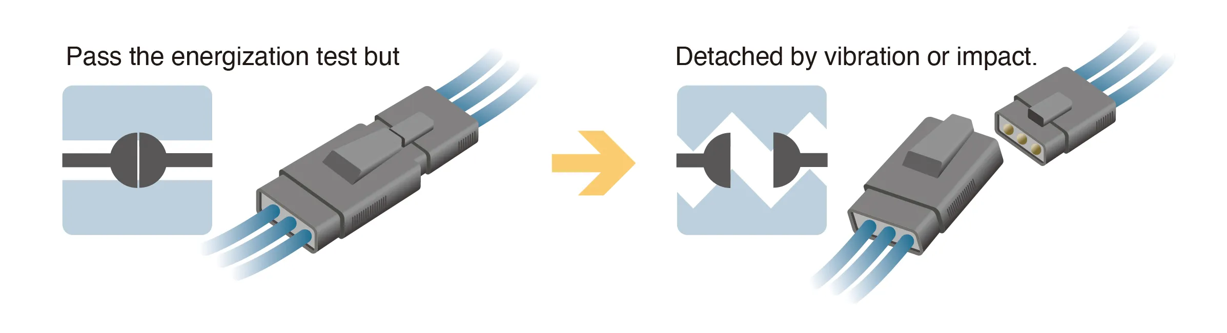
Half-fitting of the connectors means that they are normally connected in appearance but are not completely connected inside. They have mechanical and electrical contact failures, which are caused by slightly poor pushing or displacement.
A temporary electrical contact is often provided in the Half-fitting state. Some connectors may pass the energization test or electrical inspection. Because its contact is very unstable, the connectors have a risk of being easily detached due to vibration or impact.
For applications requiring the long term reliability such as onboard devices and industrial equipment, the contact failure due to Half-fitting of connectors can lead to serious failures and safety issues.
In the manufacturing process, it is important to detect the proper fitting state and take measures for it. However, it is not easy to take any measures currently due to the difficulty in determining the proper fitting state by appearance.
Three Measures
In order to reduce the risk of Half-fitting of connectors, a mechanism that can objectively and automatically detect the connection state without depending on visual inspection is required. However, those measures against Half-fitting of connectors with a high difficulty level need to be more accurate by repeating the adjustment and verification on site. Therefore, certain types of R&D efforts are often involved.
This section describes three methods as typical measures, “image inspection with a camera”, “fitting sound analysis by sound” and “mechanical check with an inspection jig”.
Image Inspection with a Camera
An image inspection with a camera is a method to photograph and analyze the position and shape of the connectors after fitting them, and then determine whether they are normally fitted. In combination with image processing using AI, this method can detect fine displacement that was easily missed in the past and incomplete connections. Also, the determination results can be recorded as images, which ensures the traceability and the quality assurance.
On the other hand, the camera inspection is easily affected by the shooting environment or detects the Half-fitting state with smaller differences in appearance with difficulty, which may cause issues in accuracy. Also it may be necessary to establish the dedicated inspection station or production line, resulting in an increase in the cost or workload.
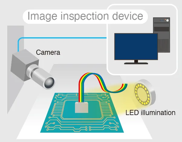
Example of system configuration
Fitting Sound Analysis by Sound
This is a method that a sensor detects a “clicking” sound and ultrasonic waves generated when fitting the connectors and then analyzes the frequency and sound pressure pattern to determine whether the connectors are normally fitted. The analysis using the sound and ultrasonic wave brings a major advantage of allowing determination without depending on appearance, and is an inspection method that is easy to use in dark or narrow places.
On the other hand, this method is easily affected by the surrounding noise and may decrease the detection accuracy in the noisy factory environment even with measures taken against noise. In most cases, a microphone is attached to the operator's arm because it is necessary to measure the sound near the connector. The risk of the lower workability and the scratches caused by a contact with the product should be also considered. It is also necessary to attach a microphone with efforts to prevent its cable from obstructing.
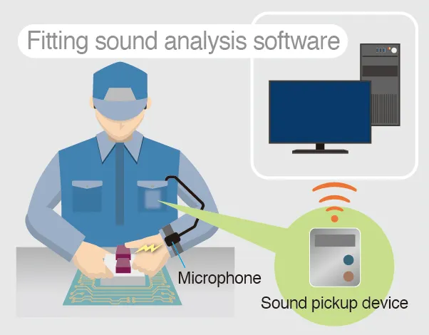
Example of system configuration
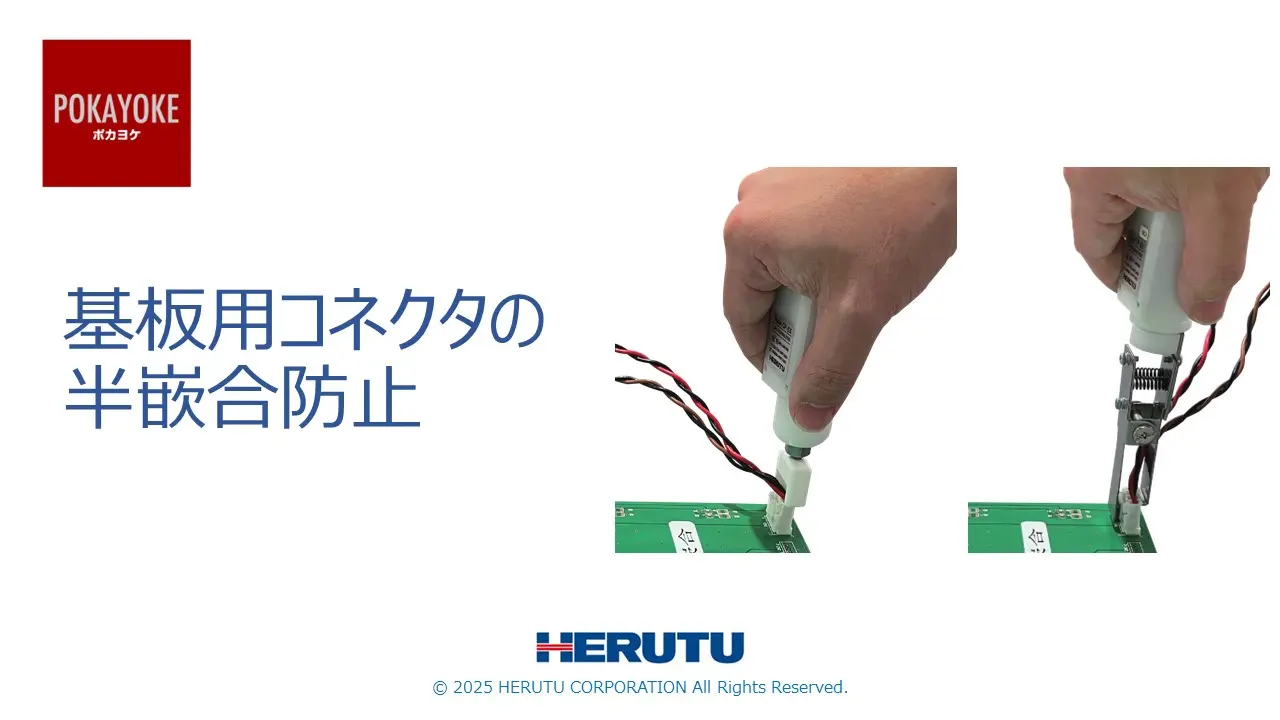
Mechanical Check with an Inspection Jig
A method using the inspection jig is the simplest and most reliable method to apply the force to the connectors actually and check the fitting state physically, which is suitable for small start. Measuring the force when pushing the jig can determine quantitatively whether the connectors are “properly and deeply connected”. Depending on the product, we provide the jigs which are not only pushed but also pulled to check whether the connectors are detached. You can flexibly select the jig according to on-site needs.
On the other hand, it is also necessary to consider the load on parts by accompanying the physical contact and the wear caused by repeated use. In addition to the fitting work, the inspection work is added. It is required to perform improvement actions on site and reduce the workload.
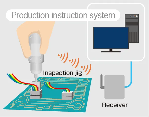
Example of system configuration
Comparison of three inspection methods
| Camera | Sound | Inspection jig | |
|---|---|---|---|
| Cost |
High Another inspection station or production line may be required |
High The software for sound processing is relatively expensive |
Slightly low A 3D printer is also available |
| Accuracy |
Slightly low May not detect some Halffitting states by appearance |
Low Depends on noise in the factory |
High Allows to inspect quantitatively it through a physical operation |
| Workability |
High The inspection process is easy to automate |
Slightly high A microphone or its cord affects the workability |
Low The inspection work is added other than the fitting work |
| Workload for installation |
High It is also necessary to coordinate the shooting environment on site and establish the inspection process |
High It is also necessary to take measures against environmental sounds on site and perform the sound pickup work in advance |
Slightly low Allow to be relatively easily installed only with design of jig |


Common Issue
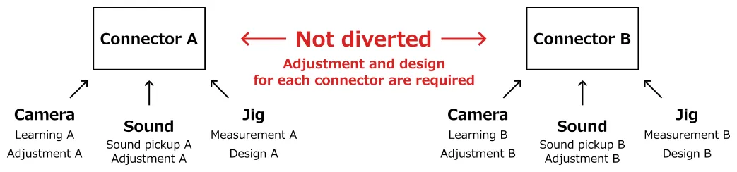
As an issue common to “image inspection with a camera”, “fitting sound analysis by sound” and “mechanical check with an inspection jig”, individual adjustment and design is required for each connector to be inspected. There are only a few mechanisms for general use. Every increase of the connector type to be inspected leads to a risk of increased adjustment and design costs accordingly.
Especially the inspection by sound requires the specialized knowledge for setting and adjustment. Therefore, it is difficult to perform that inspection in-house, and it is often necessary to outsource the inspection to another company such as system manufacturers. If you employ the inspection method that depends greatly on another company, the additional installation cost tends to be higher in performing the same inspection for other connectors.
On the other hand, the inspection jig is easily designed and produced in-house with a relatively simple structure, resulting in an advantage of keeping the initial and support costs down. Especially, such a dependency on another company becomes also a key element for the site that is required to support various types.

Another Perspective for Solving the Common Issue
The “magical” inspection method without the need of adjustment and design for each connector is not provided currently. However we can provide the measures to suppress the labor and cost to minimum.
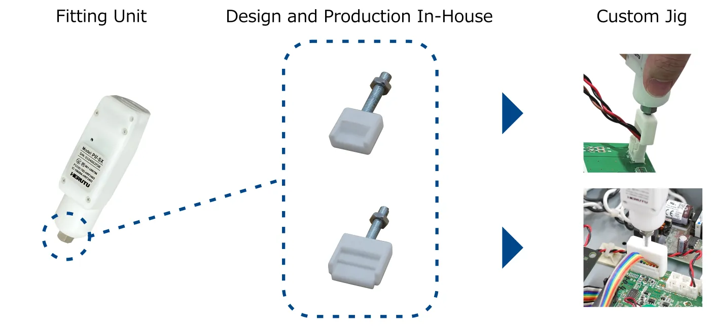
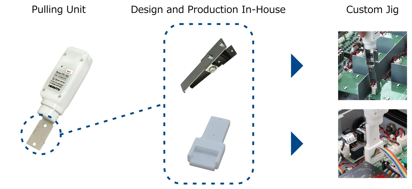
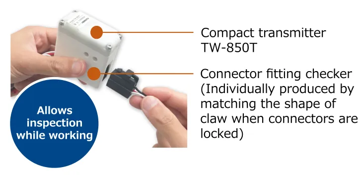
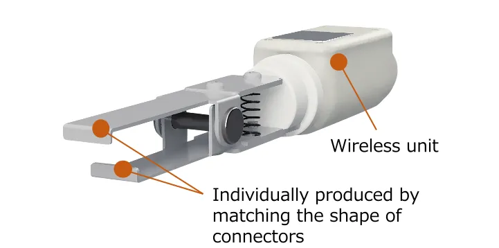
The “fitting unit” and “pulling unit” made by HERUTU ELECTRONICS CORPORATION can support the Half-fitting inspection of connectors, and have a unique feature that allows the customer to freely design a tip in contact with the connector. A degree of freedom for this design allows design and production in-house to reduce the costs.
Furthermore, you can perform customization required for each connector by repeating the trial and error in-house, which can achieve the flexible response to the environmental changes and troubles after installation. This helps solve the traditional issue of “the high cost and high dependency structure when diverting the units to other connector type inspections”.
Design and Production In-house Achieves "Cost Reduction" and "Small Start”
How to Produce the Units In-house and Take Measures against Half-fitting
Before using the “fitting unit” and “pulling unit” to describe the measures against Half-fitting, incomplete insertion and fitting failure of connectors, the operating principle of each unit is described here.
Operating Principle of the “Fitting Unit” and “Pulling Unit”
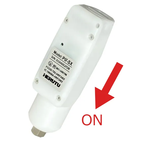
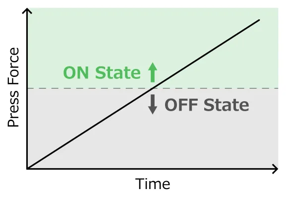
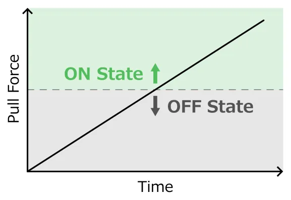
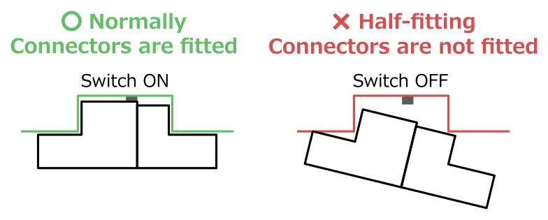
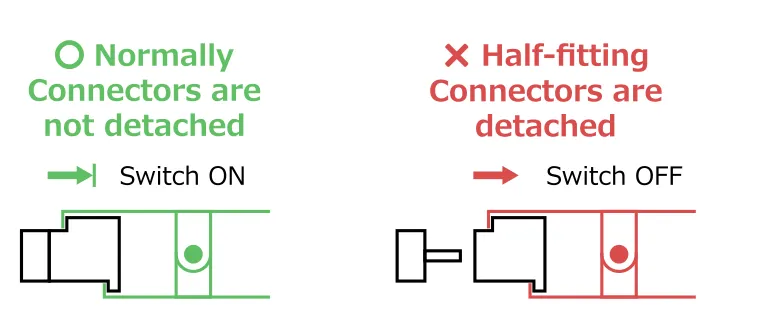
A fitting unit has a mechanism that the internal switch is activated when its tip is pressed. A pulling unit has a mechanism that the internal switch is activated when its tip is pulled.
The “fitting unit” and “pulling unit” are equipped with springs other than switches and have a mechanism that the switch is pressed only when a force exceeding a fixed value is applied. You can also select one of three springs and adjust the force depending on the connector.
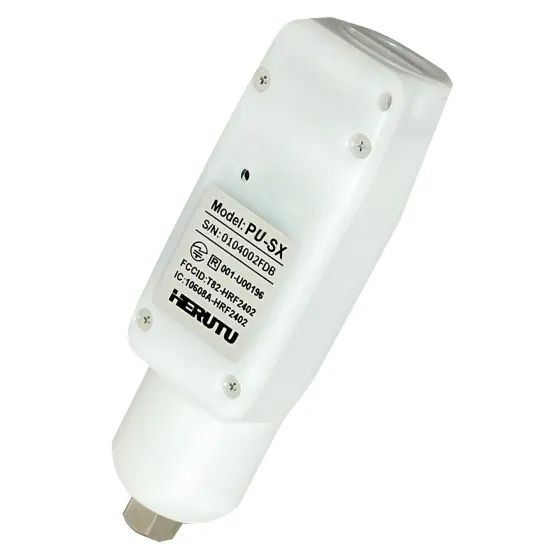
Fitting Unit
| Model | Spring Strength | |
|---|---|---|
| PU-SX10 | → | Approx. 10N |
| PU-SX24 | → | Approx. 24N |
| PU-SX48 | → | Approx. 48N |
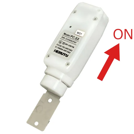
Pulling Unit
| Model | Spring Strength | |
|---|---|---|
| PC-SX15 | → | Approx. 15N |
| PC-SX30 | → | Approx. 30N |
| PC-SX45 | → | Approx. 45N |
Overall Summary
The “fitting unit” and “pulling unit” are equipped with the wireless transmitters that allow to link with the PLC or upper system using the dedicated receiver.
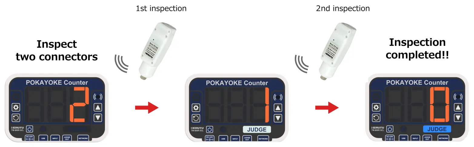
Simple Pokayoke Counter (TW-800R-SCL) can be used to build the Pokayoke system with a minimum structure allowing the number management. This can prevent not only the incompletely locked connectors from being put on market but also omission and forgetting of inspection at the same time.
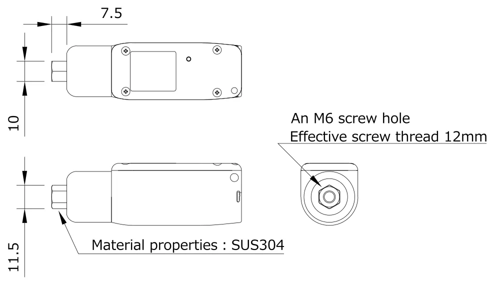
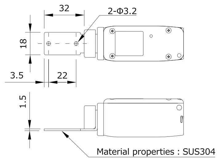
Design of Tip Parts
You can design the tip parts in-house and ask the related processing manufacturer to produce them, or use a 3D printer to produce them in-house.
This flexibility not only reduces the cost and lead time but also speeds up the processes from prototyping to implementation.
The following shows the dimensional specifications for the connection parts of the “fitting unit” and “pulling unit”.
Demo Equipment Rental Service
We offer free demo machine rentals for evaluation and verification purposes to customers considering the introduction of our products.
For demo machine rental requests, please contact our distributor or our sales department.
How to Address When In-house Production Is Determined as Difficult
When the design and production in-house are determined as difficult, you have a popular choice to outsource them.
HERUTU ELECTRONICS CORPORATION also meets these needs and produces the custom products of tip parts dedicated for the “fitting unit” and “pulling unit”.
We have the abundant experiences and proven results of custom products. Even if you do not use these units, we can design and produce the dedicated fitting inspection jigs that meet your connector specification from the ground up.


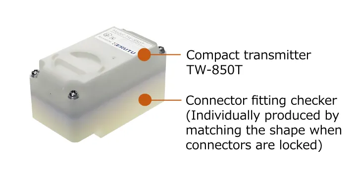
Case of Custom Product
Connector Fitting Checker ①
Connector Fitting Checker ②

Pull-Force Checker
We can provide supports in a flexible manner.
Please feel free to contact us.
Contact Us
Select the Inspection Method That Fits to the Site
| Fitting Unit | Pulling Unit | Connector Fitting Checker | |
|---|---|---|---|
 |
 |
 |
 |
| Push the connectors to check whether they are fitted |
Pull the connectors to check whether they are detached |
Check the connector shape after fitting |
Check whether a claw of connector is protruded |
| Product Details | Product Details | Click here for custom product order | |
We also provide the general catalog including other products
 Pokayoke Tools Catalog
Product Introduction Video


Please feel free to contact us regarding product inquiries, opinions, or requests.
Contact Us via Email